2D Optical ultrasound
array
System description
| Transmission ultrasound images | Transducer
field maps | Applications | References | Contact
A 2D optical ultrasound receive array based upon Fabry Perot polymer film
sensing technology has been investigated with a view to overcoming some of
the limitations associated with 2D piezoelectric arrays. These include
difficulties in fabricating acoustically small element sizes for use at MHz
frequencies whilst still retaining adequate detection sensitivity. This is
particularly so for phased arrays where, for optimum lateral spatial resolution,
a near-omnidirectional element response is required necessitating an element
size that is small in comparison to the acoustic wavelength. Sub-50µm element
sizes are required for an isotropic response at 10 MHz, for example. To achieve
this with adequate wideband detection sensitivity (<1kPa) using piezoelectric
transducers represents a major challenge. Electrical crosstalk and the
complexity that arises from the need to incorporate a large number of electrical
connections within the footprint of the array head present further difficulties.
A possible solution is to map the incident acoustic field distribution, via a Fabry
Perot polymer film sensing interferometer, on to an optical field [8,9]. The
spatial discretisation of the acoustic detection process can therefore be
removed from the detection plane to a remotely located high-density array of
optical detectors such as a photodiode array or CCD array. This offers
substantial advantages in terms of the spatial sampling of the acoustic
aperture. In particular, substantially smaller element sizes (in principle down
to the optical diffraction limit of a few µm) and interelement spacings than
can be achieved with piezoelectric arrays are possible. This approach is
currently being evaluated for medical and industrial transmission ultrasound
imaging, biomedical photoacoustic imaging and ultrasonic field
characterisation.
Back to top
System
description
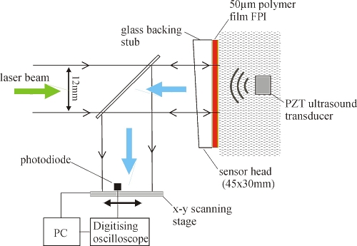
Figure 1
Experimental setup to demonstrate the concept of 2D optical ultrasound
array.
A
schematic of an experimental system used to demonstrate the concept is
shown in figure 1. A laser beam of diameter 12mm illuminates the sensing
film. Acoustically-induced changes in the optical thickness of the
polymer film produce a corresponding change in the intensity of the
reflected beam. In a practical system this would be detected and
laterally spatially resolved using a CCD or photodiode array. For the
purposes of demonstrating the concept however, a single 25MHz photodiode
was mechanically raster scanned over the area of the reflected beam to
map the incident acoustic field. To a first approximation, the effective
acoustic element size and interelement spacing are simply those of the
photodiode area and the scan increment respectively. Sensitivity was
obtained by referencing the sensor output with that of a calibrated PVDF
membrane hydrophone, giving a noise-equivalent-pressure of approximately
3kPa over a 25MHz measurement bandwidth. The bandwidth of this
particular configuration was 12MHz. The advantage of this approach is
that by using readily available inexpensive optical detector arrays with
very high element densities (e.g. a CCD array with 765x565 elements),
the sensitivity-element size limitations and often overwhelming
complexity of piezoelectric arrays can be avoided.
The system was
evaluated by two methods. Firstly, by obtaining transmission
ultrasound images of a variety of spatially calibrated targets.
Secondly, by mapping the output of a focussed ultrasound
transducer at various distances from the focus.
Back to top
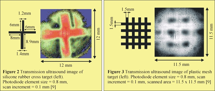
Transmission ultrasound images
Figure 2 shows
a transmission ultrasound image which was obtained by positioning the
target, a silicone rubber cross, between the sensor head and a 3.5MHz,
1" dia. planar PZT transducer and scanning the photodiode across
the reflected sensor output beam. Figure 3 shows an image of a plastic
mesh similarly obtained. The scanned region in both cases was a 12 x
12mm rectangle and the scan increments were 0.1mm. Figures 2 and 3
demonstrate the concept of mapping an acoustic field on to an optical
beam showing that a circular "array" aperture in excess of
10mm diameter with appreciable sensitivity is feasible.
Back to top
Transducer field maps
The
experimental arrangement shown in figure 1 was used to map the temporal
and lateral field distributions produced by a pulsed 5 MHz focussed
piezoelectric PZT transducer. Figure 4 shows the results obtained by
scanning the photodiode along a line perpendicular to and passing
through the axis of the transducer located above the sensor head in a
water bath. At each point of the scan the acoustic waveform detected by
the sensor was captured and linearly mapped to a grayscale. Figure 4
shows this with the curvature of the wavefront emitted by the transducer
clearly visible.
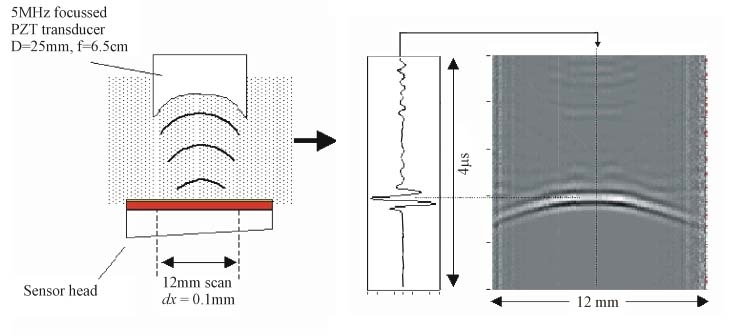
Figure 4 Line
scan through the axis of a pulsed focussed (PZT) 5 MHz transducer. The
waveform represents a profile through the centre of the image. A trigger
delay (not shown) was used so the vertical axis begins at t=28 ms
- i.e. the sensor-transducer separation was approximately 4.5 cm.
Photodiode aperture: 0.8 mm, transducer focal length: 6.5 cm, transducer
diameter: 25 mm
To obtain the
2D lateral field distribution, the photodiode was raster scanned over a
rectangular area of the reflected sensor output beam and the signal
amplitude at each step mapped to a grayscale. Figure 5 shows this for
three different distances from the focus showing the diverging beam
profile of the transducer. The FWHM values obtained from the horizontal
and vertical profiles are in good agreement with the calculated 6dB beam
widths. For example the calculated beam width at the focus (z=65mm)
is 0.67mm. The beam width obtained from figure 5 for z=70.5mm
(slightly off the focus) is 0.75mm.
Figure 4 Lateral field
distributions at 3 distances z from a 5 MHz focussed ultrasound
transducer. From left to right z=70.5 mm, z=77.4 mm, z=84.1 mm.
Transducer focal length = 65mm, element diameter = 25mm, photodiode
element size = 0.4mm, scan increment = 0.1mm
Back to top
Applications
Although the system is primarily
being developed as part of an instrument for biomedical photoacoustic
imaging, it has applications as a receiving array in several other
areas. For example it could be used in an acoustic camera to perform
high resolution transmission ultrasound imaging. In this approach the
object to be imaged is situated between an ultrasound source and a
receiving array and variations in the acoustic attenuation of the object
are imaged. The high element density and potential for rapid data
acquisition (enabling real time imaging) makes the system ideally suited
to this. Medical applications include real time imaging of joints and
joint cartilage during flexure, imaging the heel for the detection of
osteoporosis and tomographic imaging of the breast. Industrial
applications include rapid visualisation of faults such as subsurface
cracking, voids and delaminations in engineering materials and
structures used in aerospace and marine industries. Another possible
application is imaging faults in microelectronic circuits during
production. Finally, the system could be used to fulfill the need for
high speed characterisation of ultrasound transducers and arrays carried
out by transducer manufacturers and standards authorities.
Back to top
|