IMAGE GALLERY
[Tissue Mimicking Phantoms] [Tissue]
Introduction
A variety of tissue mimicking phantoms and ex-vivo tissues have been imaged using a novel backward mode photoacoustic scanner. For a detailed description of this instrument click here. Briefly however, it comprises an optical ultrasound mapping system that can be operated in backward mode – that is to say the sensor head is transparent to the excitation laser pulses enabling the photoacoustic signals to be detected on the same side of that the tissue is irradiated, an important requirement for imaging superficial targets. The system enables the photoacoustic signals to be mapped with high spatial-temporal resolution in 2 dimensions allowing a 3D image to be reconstructed. Given that photoacoustic imaging is particularly well suited to visualising blood vessels, specific emphasis has been placed on evaluating the system by imaging complex geometries composed of well defined absorbing structures such as dye filled tubes and the like. A variety of ex-vivo tissues have also been imaged, demonstrating the ability of the instrument to image vascular structures with high spatial fidelity.
Tissue
images
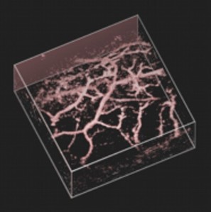
The figures below show in
vivo and ex vivo 3D images of superficial
blood vessels, obtained non-invasively using the sensing
configuration shown in figure 1 (a).
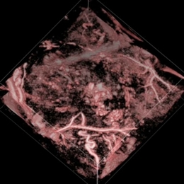
Figure 4 (above)
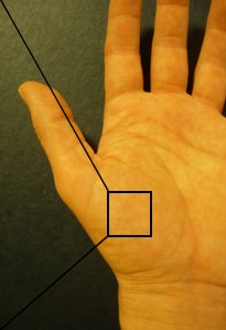
Volume rendered in vivo photoacoustic image of the
vascular anatomy in the palm of the hand. Image volume: 20mm
x 20mm x 6mm. Excitation wavelength (λ=670nm). Incident
fluence: 8mJ/cm2. No signal averaging was used.
Image acquisition time: 15minutes.
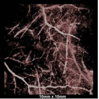
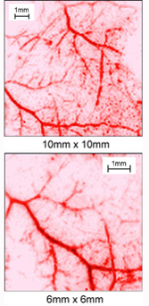
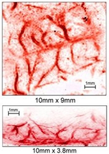
Figure
5. (top) Volume
rendered photoacoustic image of skin microvasculature.
Image dimensions: 10mm x 10mm x 4mm. (top right) Lateral
maximum intensity projection and (bottom right) expanded
view of lower left corner. Excitation wavelength Λ=590nm,
incident fluence=8mJ/cm2. No signal averaging
was used. Image acquisition time=15minutes.
 |
 |
|
|
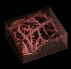
Figure 6 (above)
Volume rendered photoacoustic image of murine cerebral
vascular anatomy. Image volume: 10mm x 10mm x 3.8mm. Excitation
wavelength (λ=637nm & 800nm). The top and bottom
right images are the lateral and vertical maximum intensity
projections, respectively. Incident fluence: 8mJ/cm2.
No signal averaging was used. Image acquisition time: 15minutes.
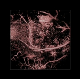
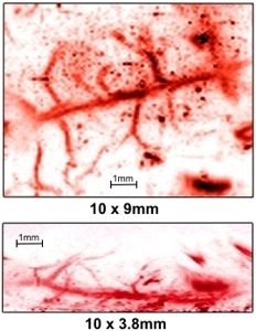
Figure 7 (above)
Volume rendered photoacoustic image of murine cerebral
vascular anatomy. Image volume: 10mm x 10mm x 3.8mm. Excitation
wavelength (λ=590nm). The top and bottom right images
are the lateral and vertical maximum intensity projections,
respectively. Incident fluence: 8mJ/cm2. No
signal averaging was used. Image acquisition time: 15minutes.
Figure 8 (above)
Volume rendered photoacoustic images of a subcutaneous SW1222 tumour (left) and a LS174T tumour (right) implanted in a mouse. Image volumes: 16mm x 16mm x 3.5mm (left) and 16mm x 16mm x 3.5mm (right). Excitation
wavelength: λ=650nm. Incident fluence: <8mJ/cm2. No
signal averaging was used. Image acquisition time: 11minutes.
Tissue mimicking phantoms
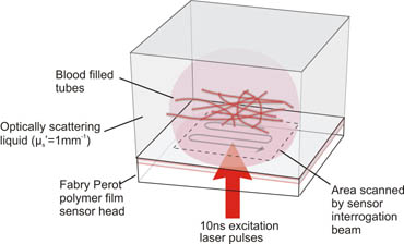
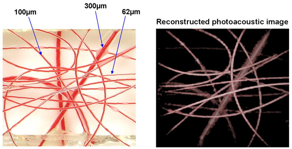
To assess penetration depth, spatial resolution and image contrast, various targets designed to mimic the optical, acoustic and geometric properties of biological tissues were imaged. An example of one such tissue mimicking phantom, designed to represent a network of blood vessels, is shown in figure 1(a). It comprises an arrangement of polymer tubes filled with blood and of inner diameters ranging from 62µm to 300µm. The tubes are immersed in a turbid liquid (Intralipid) that is designed to mimic the strong optical scattering exhibited by soft tissues. The position of the sensor head in relation to the phantom is shown in figure in 1(b). Figure 2 shows a close up of the region of the phantom that was imaged along with the reconstructed photoacoustic image. As the latter shows, the contrast and spatial fidelity is excellent demonstrating the ability of the system to image superficial blood vessels. Figure 3 shows images obtained of various other absorbing structures that were used to test the system.
 |
|
(a) |
(b) |
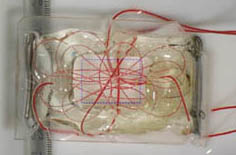
Figure 1 (a) Photograph of blood vessel tissue phantom comprising a network of tubes filled with human blood. The inner diameters of the tubes range from 62µm to 300µm. The structure is immersed to a depth of a few mm in the white optically scattering solution (µs`=1mm-1) seen in the background of the photograph. The blue dotted line indicates the region of the phantom that was imaged. (b) Arrangement of phantom with respect to the FP sensor head. The excitation laser pulses are transmitted through the sensor and into the phantom. The resulting photoacoustic signals generated by the absorption of the laser energy arrive at the sensor which is read-out by scanning a focussed interrogating laser beam across its surface.
 |
14mm x 14mm |
|
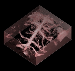
Figure 2 Photograph of blood vessel phantom (left) prior to immersion in an optically scattering liquid (Intralipid - µs`=1mm-1) and reconstructed 3D photoacoustic image (right). The tubes are located at depths within the Intralipid ranging from 0.9mm to 5.5mm. Excitation wavelength λ=800nm, Incident fluence=6.7mJ/cm2, scan dimensions: 14mm x 14mm, scan increment=100µm. No signal averaging was used.
|
 |
|
|
|
|
|
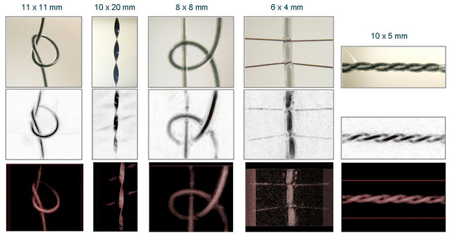
Figure 3 Photoacoustic images of various absorbing structures immersed to a depth of approximately 2mm in an optically scattering liquid (Intralipid - µs`=1mm-1). Top row: Photographs of objects prior to immersion in Intralipid. From left to right: 1. twisted black polymer ribbon; 2. 300μm bore silicone rubber tubes filled with NIR dye (μa=2.7 and 4 mm-1, respectively); 3. 300μm bore silicone rubber tube filled with NIR dye (μa=2.7mm-1) and tied with human hair; 4. Twisted pair of 300μm bore silicone rubber tubes filled with NIR dye (μa=2.7mm-1). Middle row: Reconstructed photoacoustic images - lateral maximum intensity projections. Lower row: volume rendered photoacoustic images. Excitation wavelength λ=1064nm, incident fluence=15mJ/cm2. No signal averaging was used.
|