View Control
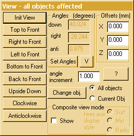
 This menu appears in the rotate and move
modes. It provides buttons for orthogonal rotations and displays the current
viewpoint and viewing offsets. Precise positioning can be achieved by typing
appropriate values into the edit boxes (and clicking on another box or
tabbing or pressing return !).These values can also be put into a batch
file for automatic display of specific orientations. Typing in angle
values requires all three angles to be entered together so a small extra
window is put up for manual entry of orientation. The orientation is achieved
by an ordered application of the three rotations.
The sensitivity of the system to mouse movement and cursor keys can
be altered by changing the angle increment (which defaults to 1 degree).
The return key must be pressed in the edit box for the increment to be
updated.
The radio buttons allow access to modes which can only be used after
the edit mode has been used to create
multiple objects. The Show Composite View button will remain greyed
until there are at least two objects available for manipulation. A composite
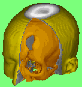
view of the other objects is displayed with the current object highlighted
to allow its relative position to be clearly understood. The rendering
in this mode is affected by the HiRes
option.
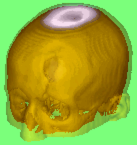
When hires is selected, images of the current and other objects are
mixed together by dithering to produce a translucent effect. It is also
possible to select an alternate rendering mode for the other objects so
that normal surface rendering of the current object can be mixed with radiographic
or mip style images of the other objects. When hires is not selected, surface
rendered images are depth sorted with the nearer surfaces obscuring more
distant surfaces.
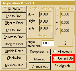
The Current Obj radio button allows access
to a surgical simulation mode. Clicking on this button changes the view
control to a mode where only the current object is allowed to move and
the frame of reference of the remaining objects remains static.The control
menu changes  to
show its altered function. Extra buttons (like those in the edit
mode) are included to allow change of the current active object,
mirroring of any object. and selecting which of the available objects
will be incuded in the composite image. All orientation changes
on the object can be removed with the re-align obj button which
restores the current object to its default orientation. The numeric displays
of angle and offset relate to the composite orientation and cannot change
in this mode. The only exception to this is the initial view button which
will restore the front view of the composite data set. Having edited a
data set, the save edit option in the file
menu allows the information to be saved to a disc file for later retrieval.
Back to index
Resize Control
 This window appears
in the resize mode. It displays current scale
both as image resolution and as field of view. Either field may be selected
and updated from the keyboard by direct numeric entry (and clicking on
another box or tabbing or pressing return !). These values are updated
when resizing with the mouse or cursor keys in the main window.
Back to index
Backcull
Control
 This
window appears in the back cull mode. It displays the depth of the back
cull face in mm. Negative values are behind the current centre of rotation.
The depth may be selected and updated from the keyboard by direct numeric
entry (press return !). This value is updated when moving the plane with
the mouse or cursor keys in the main window. This mode can assist in appreciating
the relative depths of parts of the object in view and in determining foam
sizes for milling.
Back to index
Crop Controls
The crop controls are a quick way of removing parts of the data set
from the display but are restricted to the original axes of the data, only
allowing entire slices or strips to be ignored. The actions of the mouse
and keyboard controls are aligned with the default orientation of the data.
If there is any confusion it is advisable to restore the initial view
orientation before proceeding. If you want to restore the full object this
can always be done in the 3D edit mode. When
measuring surface areas or saving STL
files, this mode of editing should NOT be used as it will cause incorrect
results by failing to include the cut surfaces during processing..
Back to index
©1997-2004 Robin Richards, Medical Physics, U.C.L.
All rights reserved.
 This menu appears in the rotate and move
modes. It provides buttons for orthogonal rotations and displays the current
viewpoint and viewing offsets. Precise positioning can be achieved by typing
appropriate values into the edit boxes (and clicking on another box or
tabbing or pressing return !).These values can also be put into a batch
file for automatic display of specific orientations. Typing in angle
values requires all three angles to be entered together so a small extra
window is put up for manual entry of orientation. The orientation is achieved
by an ordered application of the three rotations.

 to
show its altered function. Extra buttons (like those in the
  This window appears
in the
  This
window appears in the back cull mode. It displays the depth of the back
cull face in mm. Negative values are behind the current centre of rotation.
The depth may be selected and updated from the keyboard by direct numeric
entry (press return !). This value is updated when moving the plane with
the mouse or cursor keys in the main window. This mode can assist in appreciating
the relative depths of parts of the object in view and in determining foam
sizes for milling.